
Inspiration

In class we looked at so many different types of project enclosures, all inviting the viewer to press, switch, open, close, whatever. I wanted my enclosure NOT to invite the viewer to press the button. Because I’m me, of course I wanted something to happen when the button was inevitably pressed, so I began spinning a story...
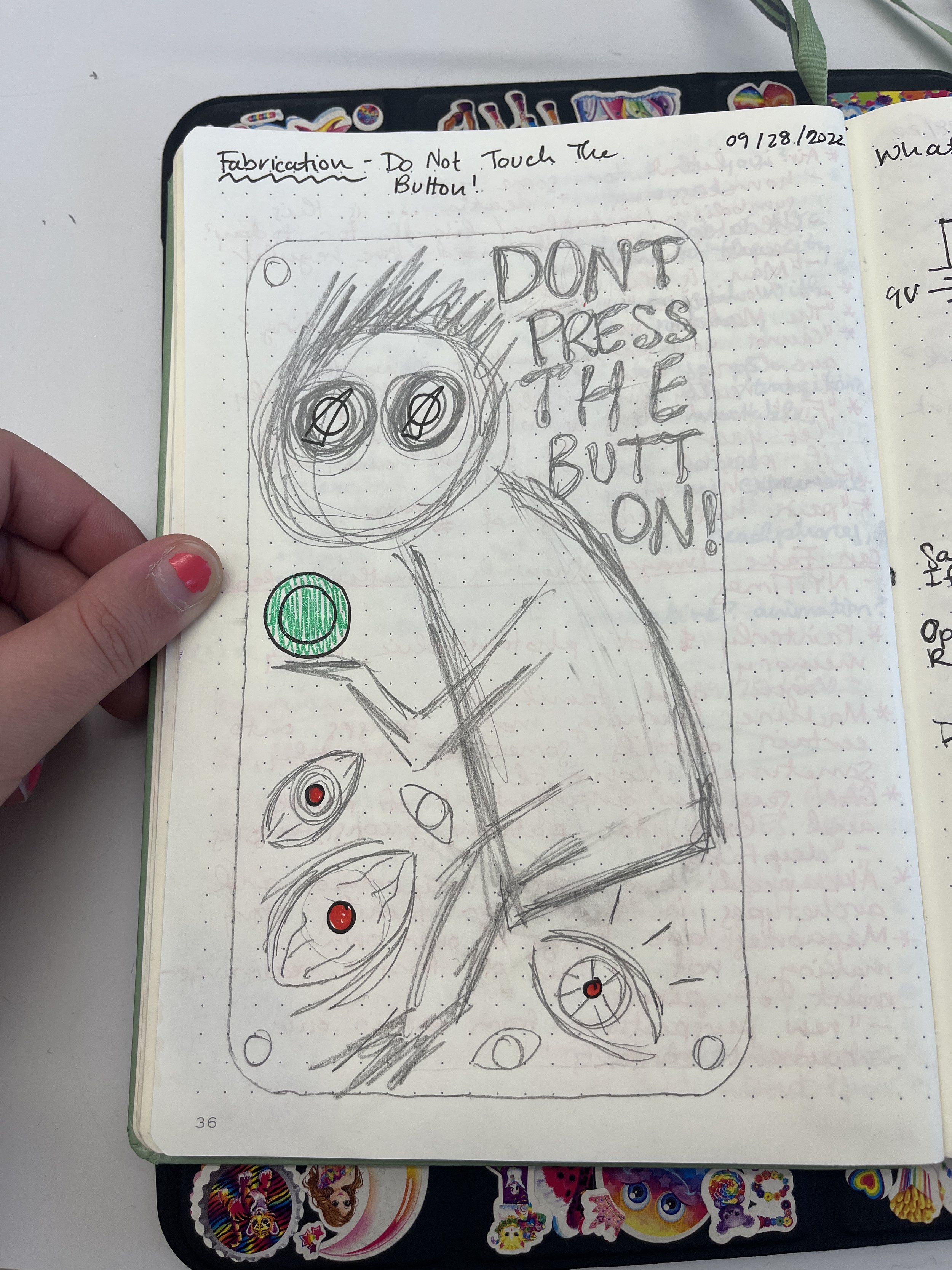
I like adding an illustrative element to my projects sometimes so I thought of a sad, weird, squiggly guy begging to not press the button. At first I wasn’t sure where I dug this imagery up but Olive reminded me my drawing was very Salad-Fingers-esque; a YouTube series from my childhood that apparently still haunts me.
Drawings

Materials
Circuitry:
Breadboard
9V battery
Barrel jack
x2 2.5k ohm potentiometer
x2 white knobs
x2 100 ohm resistors
x3 red LEDs
Green push button
Wire
Heat shrink
Enclosure:
Wood from the free shelf
x4 1.5 inch stand offs
x8 6-32 screws
Tacky putty
Tools
Enclosure:
Laser cutter
Tape measure
Calipers
Dremel
Hex key
Clamp
Design:
iPad and Apple Pencil
Illustrator
Circuitry:
Wire cutters/strippers
Tweezers
Soldering iron
Hot air gun
Process
First things first, make sure my engineering background hasn’t failed me: prototype the complete circuit to go along with my drawing. Here, a 9V battery is powering my circuit. Pressing the button turns the three red LEDs on. Two potentiometers change the brightness of the LEDs.

Electronics prototype
Once the electronics sanity-check was completed, I could work on getting my drawing into Illustrator. I started with drawing two rectangles that would fit the breadboard. Then I transitioned to my iPad and the trusty blob brush tool to hand draw the engravings on the box. Then I measured my panel mount components with some calipers and added holes to place them on the surface. Ctrl+P on the Epilog <3.

Illustrator drawing

Laser cut enclosure faces

Next, I tore my electronics from my prototype and got them ready for mounting. I soldered wires to the two potentiometers and the LEDs. To mitigate bare leads touching each other, I heat shrinked the LED legs. Now I was ready to install my electronics on my enclosure! Or so I thought…


Ummmmm SO WHAT THE HECK ARE THESE?! I never noticed this little nub, but I guess panel-mount potentiometers have this indicator to identify their orientation. Not sure I really get their use, but this was getting in the way of installing the dials on the top face. Ideally I would have laser cut a hole for the nub to slot into but at this point I just went in with a Dremel and made some extra nub space. It’s not perfect, but it works!

Last but not least, I attached the retro white knobs to the potentiometer dials. I needed a super small hex key to tighten the set screw. I fixed the breadboard and battery onto the bottom plate with some tacky putty. Then I plugged all my wires back into my bread board circuit and screwed the top plate into place. Voila!
Final Product

Conclusion
In class last week we learned that project enclosures should be 1. easy to open 2. easy to modify 3. easy to make multiples 4. cheap. I think I hit basically all of those requirements. I only spent like $12 on the batteries, but I am very privileged to have access to the ITP shop where it’s stocked with all the supplies and tools I could ever need.
In the future, I’d like to add rubber feet to the bottom of this enclosure. I’d also like to take a good quality video showing how my project works (or shouldn’t?! Don’t press the button!). I also feel like I should revisit my circuit. Ideally, I’d like the knobs to dim the LEDs even more but my brain hurts too much right now to figure out why my circuit doesn’t work right.
Resources
https://learn.adafruit.com/all-about-leds/adjusting-brightness