
For my final project for my Creative Coding class, I wanted to flex my Processing skills and pair them with my expertise in hardware. I came up with the idea to create a magic mirror in which a scene from my computer’s web cam is reflected onto a LED matrix using Processing’s serial library.

Process
Prepare hardware
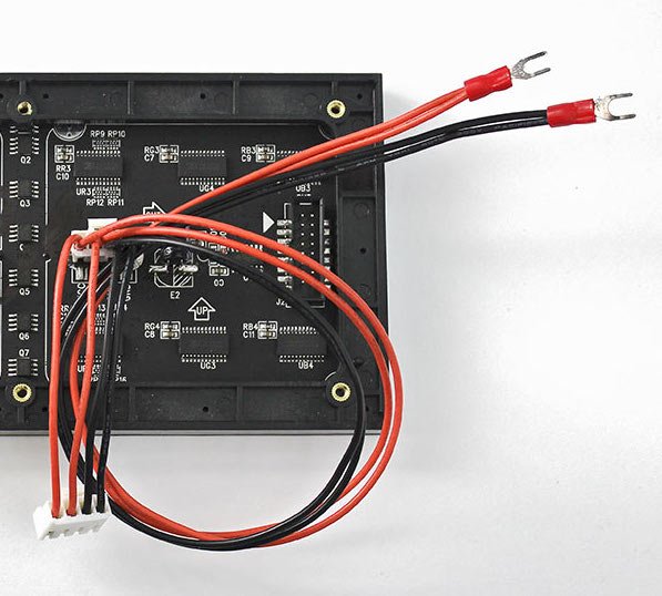
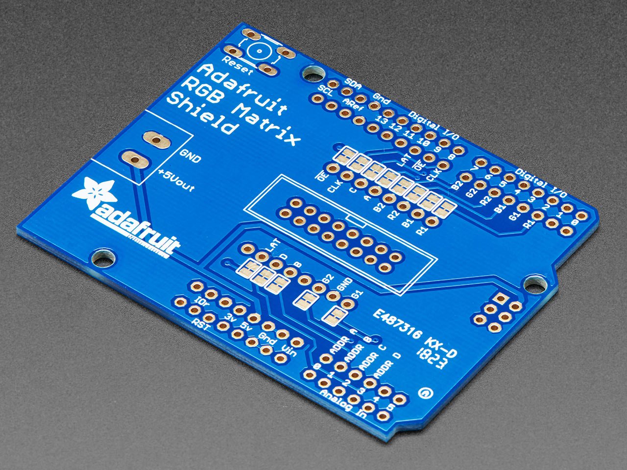
Before writing code, I needed to make sure the hardware was ready to be connected into a system. Adafruit’s RGB matrix shield comes in separate parts (ugh!) so I needed to solder on the through-hole components: headers, reset button, power terminal, and 16-pin connector which connects to the RGB matrix circuitry. I also chopped up my power supply and soldered/shrink-tubed 5V and GND to the spades terminals of the RGB matrix’s power cable.

Prepare software
After the hardware was setup, I got the Arduino IDE situated. Following the RedBoard Turbo hookup guide, I downloaded the “Arduino SAMD Boards (32-bits ARM Cortex-M0+)” and “SparkFun SAMD Boards” in the boards manager. For good measure, I restarted the IDE and I flashed the “Blink.ino” example and made sure it was working properly.

Try out LED Matrix
Adafruit also provides a handy guide for getting started with the RGB Matrix. From there I downloaded the “RGB Matrix Panel” library and “Adafruit GFX library” using the Arduino library manager. I plugged the matrix shield into my RedBoard, RedBoard into my computer, ribbon cable from matrix to shield, and matrix power cable into a power strip. At this point I was ready to test the “colorwheel_32x32” example.
Get communicating
I was lucky once again that my company had a tutorial for setting up serial communication over USB between Processing and Arduino. I followed the steps to get Arduino sending messages to Processing and vice versa.
Update LEDs using Processing
Now that hardware, software, and communication was tested, I could start updating the matrix over serial. Looking at Adafruit’s library for the matrix there are different color functions to update the LEDs: color333 for 3-bit, color444 for 4-bit, and color888 for 8-bit RGB precision. I paired this with the library’s fillScreen() function, drew some rudimentary buttons in Processing, and Arduino listened for serial messages.
Time to bring in the web cam
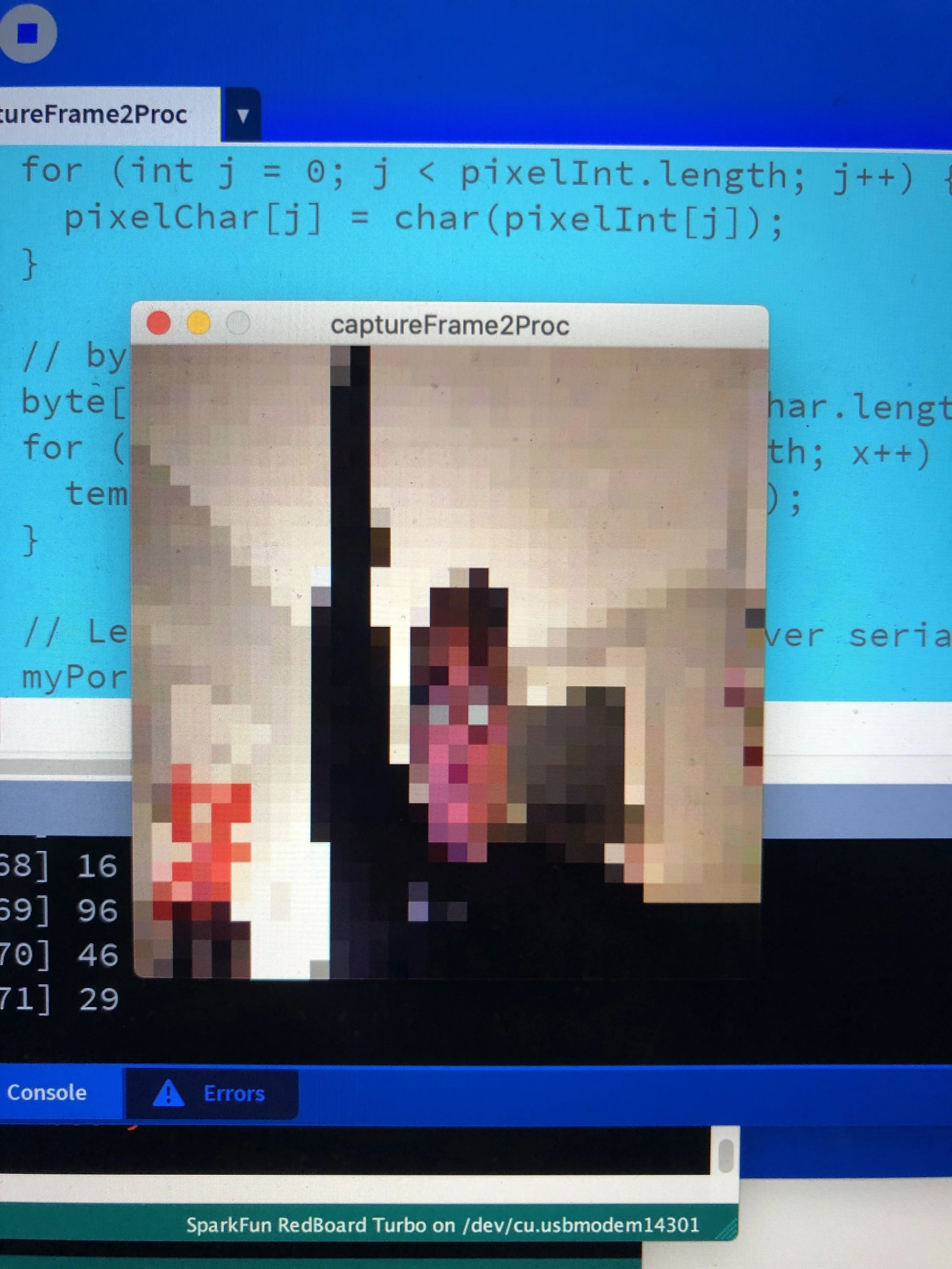
There are a lot of handy examples that got me started with the Processing Video Capture library. The first thing that I had to do was divide up my web cam feed into 32 by 32 pixels which represent one LED on the matrix each. I loaded the color values into an array using Processing’s loadPixels() function. Before this project, I wasn’t aware of the color datatype. I then extracted the RGB elements of each pixel and put them in a new array sequentially. This is the data I decided to send over serial to the RedBoard Turbo.
Bugs and WIP
I definitely had some hardware weirdness while trying to get this project to work. I personally rely on Arduino’s serial monitor to do a lot of my debugging, so one MAJOR drawback was not being able to use that because the serial port was busy talking to Processing. I also had issues with the SAMD21 occasionally not showing up as a COM port or not being able to upload code because the serial port was still communicating with Processing. You have to stop the Processing code!
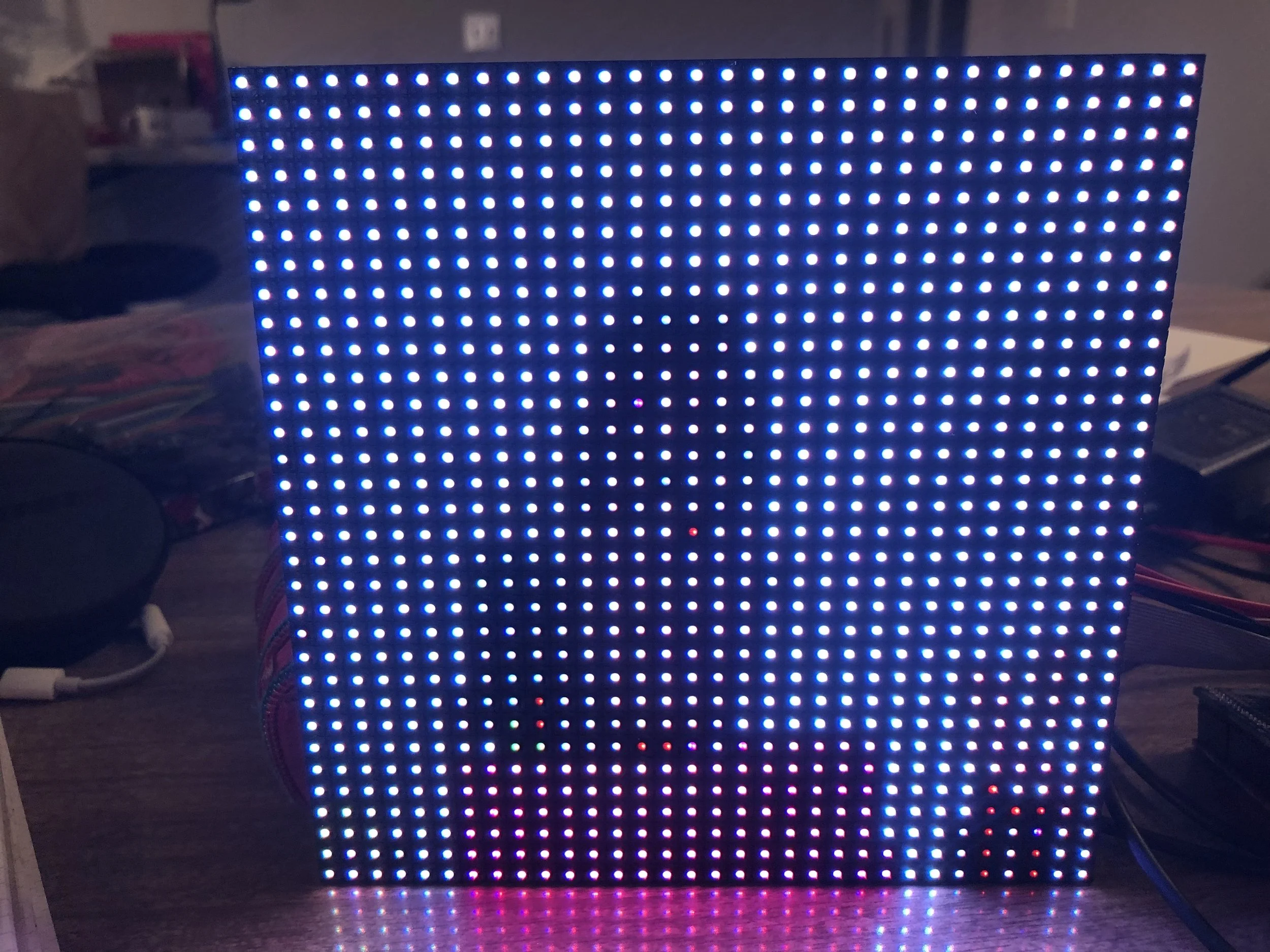
Another road block appeared when trying to read and write the array of RGB values (ints) over serial. The video below shows the data not coming in correctly. The colors and the number of pixels illuminated are all buggy. Some internet digging recommended converting the ints to raw bytes which ended up working for me. I’ve got an example showing how to convert, send, and receive byte arrays. Massaging the baud rate on both the Arduino and Processing sides (it’s gotta match!) and how frequently I was sending data helped smooth out the RGB matrix response.


Me looking into my webcam. The matrix really abstracts the web cam image. It took me a second to realize my code was actually working!
Final Product
All the code for this project lives in this Github repo.
The code is separated by platform. The idea is to run matching named sketches in Arduino and Processing at the same time to recreate this project. I’ve numbered the examples in the order that I learned the concepts in: most basic building block to the full magic mirror.
Below are a couple of images of the RGB matrix reflecting my laptops web cam data.


Future Additions
The original idea for this project was something more dynamic and reactive, more like a mirror. So my first investigation would be into the limitations of the baud and data rates. Ideally, this would be an interactive art piece, so if a viewer can’t notice the LEDs updating they won’t know what they are looking at.
I also think it’s kind of hard to make out what exactly is represented on the matrix. Especially with all the white in the background. I think it would be interesting to abstract the image a bit more by experimenting with frame differencing or background subtraction to see if that makes for a more compelling effect.
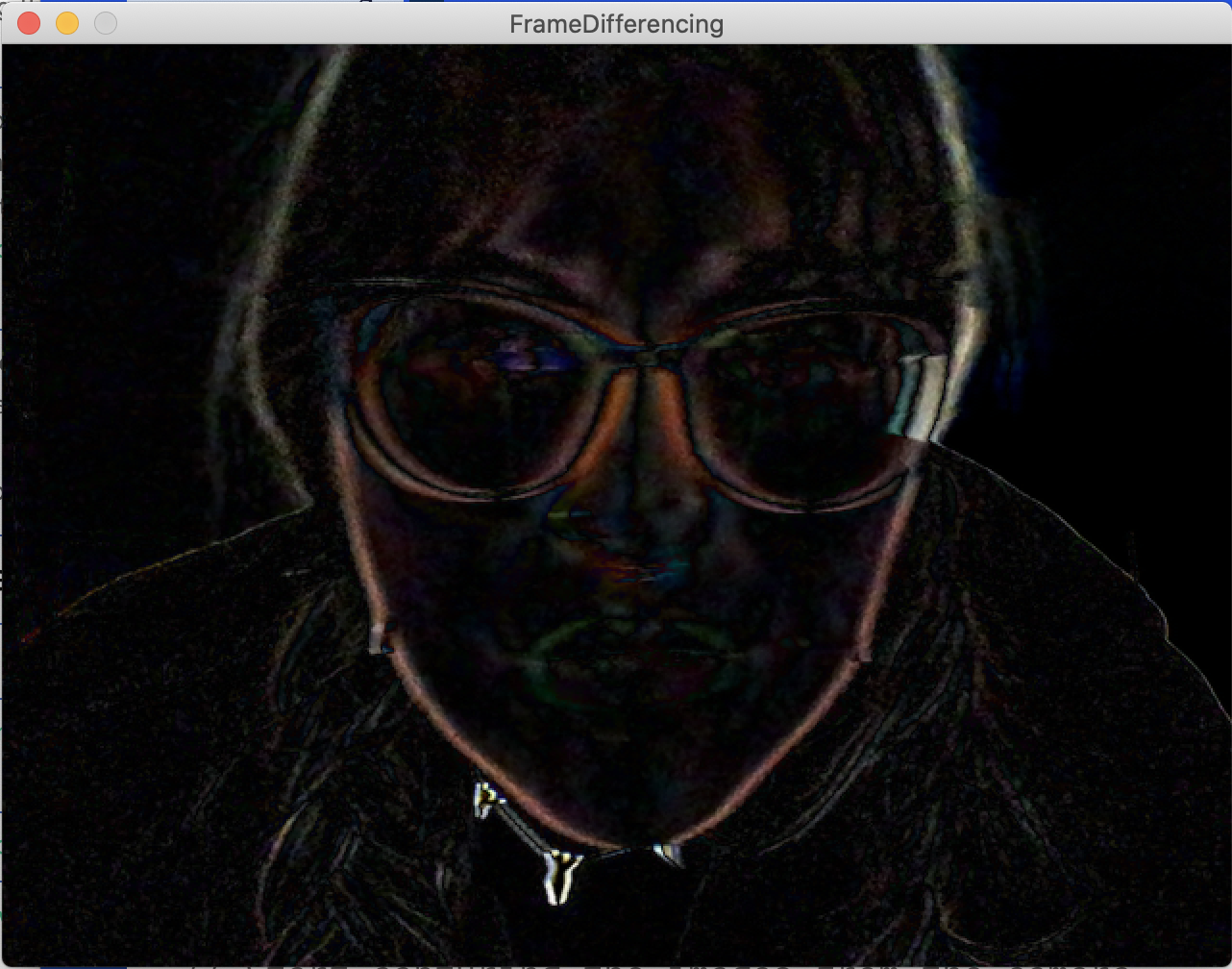
Frame differencing

Background subtraction
Lastly, I’d want to this to be as much of a stand-alone piece as possible, something that could be installed in a gallery. I don’t know if that would mean using a kinect instead of a web cam. Also building some sort of housing for the hardware and a “frame” for my “mirror” would be the finishing touches to my art piece!
Additional Resources Used
https://processing.org/reference/
https://discourse.processing.org/t/serial-write-print-more-than-one-byte/12159/2
https://www.delftstack.com/howto/arduino/arduino-char-to-int/
https://discourse.processing.org/t/how-do-i-write-a-uint8-t-data-array-via-serial/30543/2